
Arduino PWM LED Control Kit Price in Pakistan | AmpFlick
$ 6.47
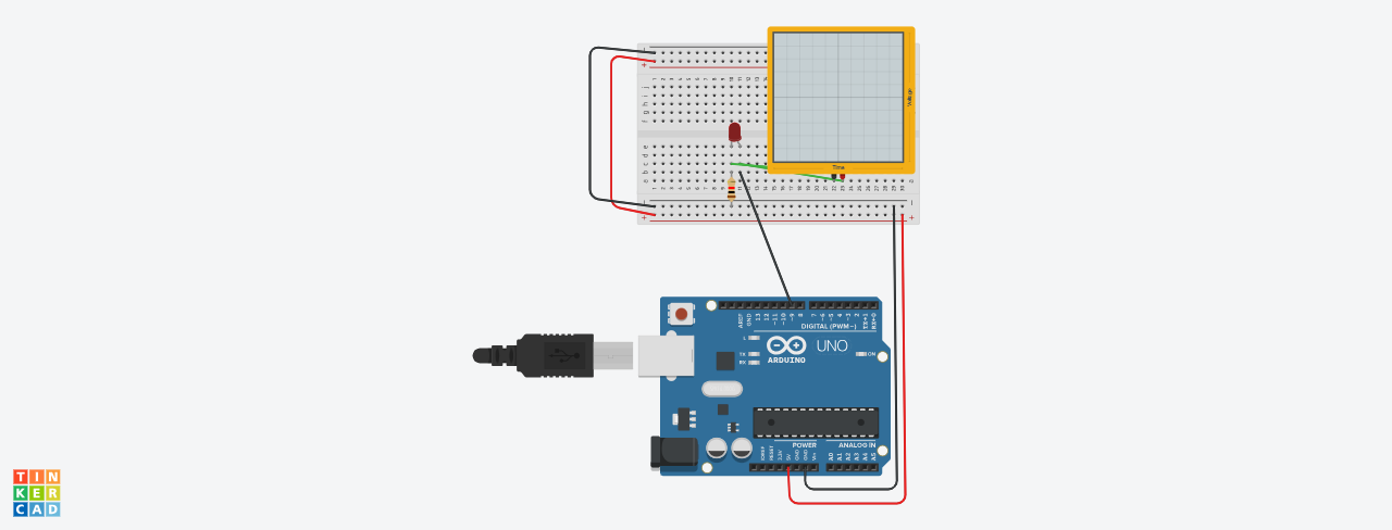
Description Master Signal Analysis with the Arduino PWM LED Control Kit This professional educational set allows engineers to visualize pulse width modulation in real-time. Therefore, using the Arduino PWM LED Control Kit is the best way to bridge code with physical wave forms. The system utilizes an Arduino UNO to generate varying duty cycles across digital pins. Additionally, the included high-precision 220-ohm resistor ensures the LED operates within safe current limits. However, the true value lies in using an oscilloscope to monitor these high-speed voltage transitions accurately. Technical Specifications for Arduino LED Control Kit Controller: Arduino UNO R3 with ATmega328P microcontroller core. Prototyping: 400-point solderless breadboard with standard 2.54mm pitch. Resistance: 220 Ohm 1/4W carbon film resistor with 5% tolerance. Analysis Tool: Digital storage oscilloscope compatibility for frequency and duty cycle measurement. Voltage: Stable 5V DC logic level operation. Usage and Waveform Calibration First, seat the Arduino and LED onto the breadboard firmly. Connect the resistor in series to the digital PWM pin. Then, attach oscilloscope probes across the LED terminals to observe the square wave. Arduino PWM LED Control Kit Circuit Diagram This diagram shows all kit components connected to simulate working. Advantages and Disadvantages of the Arduino PWM LED Control Kit Pros: Provides immediate visual and graphical feedback of signal modulation techniques. Furthermore, it supports deep technical understanding of power regulation through software. Cons: High-end oscilloscopes required for analysis are sold separately from this basic kit. Precautions and Safety Tips Always verify the common ground between the Arduino and the oscilloscope. Never exceed the 5V limit on the digital input pins to prevent damage. What is Included in the Package 1x Arduino UNO Compatible Board 1x 400-Point Solderless Breadboard 1x 220 Ohm Resistor 1x 5mm High-Brightness LED AND PLEASE NOTE THAT ALL COMPONENTS ARE UN-ASSEMBELED. You have to assemble the kit your self. DRIVE LINK FOR .ino FILE AND CIRCUIT DIAGRAM: Click Here Tutorial on how to use this: Click Here Order more Kits from AmpFlick: Click Here �� Connect with the Ampflick Community Stay updated with the latest hardware arrivals, project ideas, and engineering mentorship in Pakistan! Instagram: @Ampflick — Daily project reels & hardware fashion. LinkedIn: Ampflick Tech — Professional networking & career opportunities. WhatsApp Support: Link to WhatsApp — Technical queries and bulk orders. YouTube: Ampflick Official — Hardware masterclasses.