Servo Control Module
$ 5.22
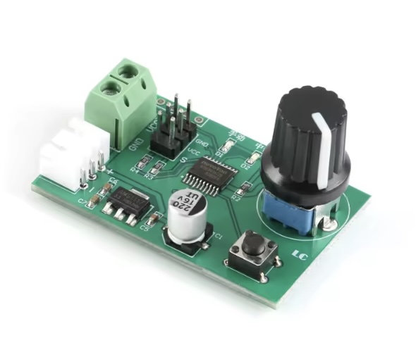
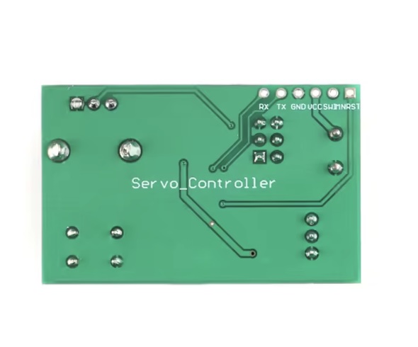
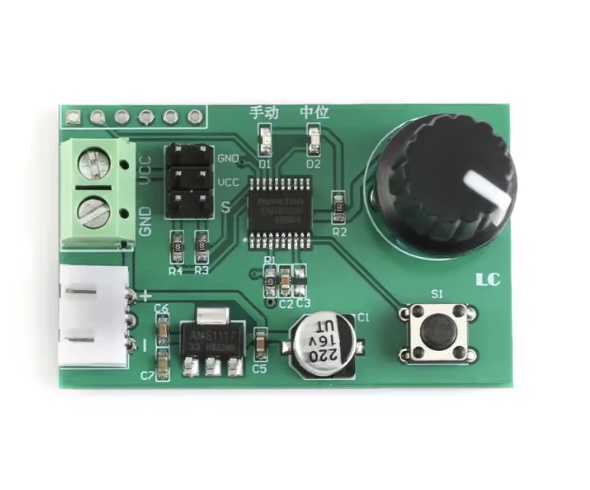
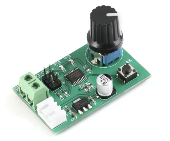
Description The onboard stable 8-bit MCU is used to generate high-resolution PWM signals with precise control. Support manual mode and return to medium mode, switch by button, with mode indicator. Support knob adjustment or serial command control in manual mode. The serial port command control can use the matching host computer software or connect to the external MCU. Number of control channels: 2 channels (M0 and M1 servos). When using the knob adjustment and return function, the 2 servos are controlled at the same time. When using the serial command, the 2 servos can be controlled separately. Steering gear control accuracy: 0.09 degrees (that is, PWM minimum change value 1us) Support steering gear with control period of 20ms and pulse width in the range of 0.5-2.5ms (such as Futaba, Huisheng, etc.) Can directly use 2S lithium battery charging head to debug and return to the steering gear Power supply voltage range: 5-9V (Based on the actual servo supply voltage) Product size: 47.2*29.8mm Manual: About wiring: VCC, GND connect to power, insert the servo into the 2X3P pin header, where VCC is positive, GND is negative, and S is signal. (The Steering gear are not includes) Manual mode: The manual mode is selected by the onboard button, at which time the manual light is on and the neutral light is off. The manual mode includes knob control and serial port control. The default is knob control. The two control modes will automatically switch, that is, when the potentiometer is detected to rotate, the knob is selected. When the serial port receives a valid control command, the serial port control is selected. Knob control: Directly turn the potentiometer to control the steering gear to rotate in the range of 0-180° Serial port control: The onboard MCU can receive and analyze the servo position command sent from the host computer, external MCU and other devices (baud rate 9600, compatible with 3.3V/ 5V level), thus controlling the 2-way servo respectively, where the servo position command format For: #P!, The respective meanings are as follows: a, # is the starting symbol, indispensable. b, indicates that the number of steering gears controlled, total 2 channels (range: 00-01 corresponds to servos M0 and M1 respectively); c, P is a fixed symbol in the instruction format, which is indispensable. d, indicates the width of the PWM multiple (range: 0500-2500 corresponds to 0-180° respectively). e, ! is the end symbol of the instruction, indicating the end of an instruction, which is indispensable. For example: Send #00P1500! to turn the servo M0 to 90° position Send #01P1000! to turn the servo M1 to 45° position For example. First, prepare a USB to _TTL serial port module (such as CH340, FT232, etc.). The TX, RX and GND of the serial port module are respectively connected to the RX, TX and GND of the control board. select a correct port number, after the connection is successful, drag the 0 and 1 progress bars to control the M0 and M1 servos respectively. Back to medium mode: The back to medium mode is selected by the onboard button. At this time, the manual light is off, the neutral light is on, and the servos M0 and M1 are simultaneously returned to the neutral position. Board interface description: VCC, GND: power interface; XH2.54mm carrier: backup power interface, can be connected to 2S lithium battery; 2X3P pin header: 2-way servo interface; TX, RX: UART serial port pins; SWIM, NRST: Reserve the MCU program download port. Note: Because the steering gear is a relatively power-consuming device (such as the MG995/MG996 steering gear), the power supply current to the steering gear needs to be sufficient. If the on-board LED flashes when the steering gear rotates, the steering gear is not controlled or the error When the abnormality is abnormal, the power supply current is insufficient and the power supply needs to be replaced. Packing List: 1 x Servo Control Module